
TIC S 3002 P - Motorhome heating TRUMA - Free user manual and instructions
Find the device manual for free TIC S 3002 P TRUMA in PDF.

| Product type | Gas motorhome heater |
| Brand | TRUMA |
| Model | TIC S 3002 P |
| Recess dimensions | 480 x 480 mm (cutout for combustion air: 205 x 100 mm) |
| Weight | Approximately 12 kg |
| Power supply | Butane/propane gas |
| Operating pressure | 30 mbar (28 mbar butane / 37 mbar propane) or 50 mbar |
| Ignition | Piezoelectric (depending on version) or automatic |
| Main functions | Fan-forced heating with thermostat, temperature regulation |
| Safety | Thermostat probe, ignition safety valve, exhaust of burnt gases to the outside |
| Maintenance and cleaning | Exterior cleaning with a soft cloth; annual inspection by a professional |
| Spare parts | O-ring, exhaust hose AE3/AE5, roof chimney, igniter, thermostat probe |
| General information | Installation in wardrobe, external combustion air, use while driving possible under conditions (outside Germany) |
Frequently Asked Questions - TIC S 3002 P TRUMA
User questions about TIC S 3002 P TRUMA
0 question about this device. Answer the ones you know or ask your own.
Ask a new question about this device
Download the instructions for your Motorhome heating in PDF format for free! Find your manual TIC S 3002 P - TRUMA and take your electronic device back in hand. On this page are published all the documents necessary for the use of your device. TIC S 3002 P by TRUMA.
USER MANUAL TIC S 3002 P TRUMA
Installation instructions
Installation and repair jobs on the heater are only to be carried out by an ex
pert. Read and follow the installation instructions carefully prior to starting any work!
Intended use
This heater is designed for installation in caravans, mobile homes and other trailer vehicles. It is not approved for installation in boats. Other forms of use are also possible after consultation with Truma.
Approval
Declaration of conformity:
The Trumatic S has been approved by the DVGW and complies with the EC guidelines (90/396/EWG) for gas appliances as well as with the associated EC guidelines. The product ID No. for EU countries is:
S 3002 (P): CE-0085AP0325
S 5002: CE-0085AP0326
The heater is approved for installation in areas frequented by people (in motor vehicles) and, provided the rules and regulations of the respective country are observed, it can also be used while the vehicle is moving.
Information regarding installation in Germany: This heater is not to be installed in motor vehicles (e.g. mobile homes) which are to be registered in Germany.
Truma heaters Trumatic S 3002 K, Trumatic C or Trumatic E are intended for motor vehicles. These have been approved by the German Federal Office for Motor Vehicles.
For other countries the special instructions must be observed when installing the heater in mobile homes (refer to „Special installation instruction").
Installation of the heater inside buses or in vehicles for the transportation of hazardous goods is not permissible.
For installation in special-purpose vehicles, the regulations applicable in each case must be observed.
Regulations
Any alteration to the appliance (including exhaust duct and cowl) or the use of spare parts and accessories which are essential for the operation of the heater and are not original Truma parts, or the non-observance of the installation and operating instructions, will lead to the cancelling of the guarantee and exclusion of liability claims. It also becomes illegal to use the appliance, and in some countries this even makes it illegal to use the vehicle.
The first year of operation must be marked on the name plate.
Installation in vehicles must accord with the technical and administrative provisions of the individual country of use (e.g. EN 1949). National specifications and regulations (in Germany, for example, DVGW Worksheet G 607) must be respected.
In other countries always observe the respectively valid regulations.
Further details of regulations in various countries of destination can be obtained from our foreign representatives (see Operating Instructions).
The combustion air must not be taken from the vehicle interior. The combustion air must always be obtained from the outside.
Choice of location
-
Always install the appliance and its exhaust gas duct in such a way that it is easily accessible for service work at all times and can be removed and installed easily.
-
As a rule, the heater should be installed inside the wardrobe in the vehicle.
Installation cut-out:
S 3002 (P): 480 × 480 ~mm
S 5002: 510 mm wide,
522 mm high.
For satisfactory operation of the heater it is important that the heater base and bottom
edge of the installation box are assembled on one level so that the control knob is flush with the casing.
- Using the installation template, check whether the floor cut-out section (S 3002 (P) 205 × 100 ~mm , S 5002: 235 × 230 ~mm ) for the combustion air intake is to be on the right or on the left, under the appliance (fig. A shows right-handed installation, fig. G left-handed installation). The combustion air intake is not to be located in the spray area of the wheels (if necessary fit a spray guard).
There should be no heat-sensitive materials under the appliance (cut away carpeting). In the case of PVC flooring, the heating of the heater base may cause some discoloration.
Fig. B: If the heater is installed on a plinth or the like, the intake extension (art. no. 30030-04800, length 50~cm ) must be used. The intake extension must be freely suspended in the air flow approximately 5 to 10cm below the lowest point of the vehicle (shorten if necessary). Two intake extensions are required for the Trumatic S 5002.
The plinth must be sealed from the vehicle interior and must not be made from a combustible material or has to be lined on the inside with sheet metal because of the risk of blow-back under unfavourable wind conditions. To prevent non-burned gas from building up the plinth must have a vent at least 2cm^2 in size at its lowest point, or must be open at the bottom.
- Exhaust ducts and cowls must be installed in such a way that exhaust gas cannot find its way into the vehicle.
To ensure even and rapid warm air distribution as well as lower surface temperatures on the heating unit, we recommend installing a Trumavent warm-air system.
If desired, the Trumatic S 5002 heating system is also available with a special installation box for two.
Trumavent fans.
Preparatory work and installation boxes
-
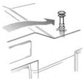
Secure the template for the floor opening in the cut-out section by means of thumb tacks, the arrow must point exactly to the front edge of the opening (R = right-hand installation, L = left-hand installation).
-
Cut the floor opening using a saw and pre-drill 5 holes for the fixing screws. The exact dimensions must be observed!
-
Fig. A: Insert half-frames (5) in the floor opening and press them outwards and screw tight (pretension as needed by bending the sides upward so that the frame fits firmly).
-
Fig. D: Break out the prestamped apertures for the waste gas pipe on the outer part of the installation box (R = right-hand installation, L = left-hand installation). If the installation depth is small, the waste gas pipe can also be conducted through the side with the S 5002 heating system (R1 or L1).
When installing the special pipe for internal gas connection (refer to „Gas Connection”), break out both apertures.
If a Trumavent fan and/or Truma-Ultraheat electrical supplementary heating are being fitted, remove the pre-stamped cover (T) or (U) respectively, and fit the units to the installation box in accordance with the installation instructions provided in each case.
- Fig. C: Separate the outer part (1) and inner part (2) of the installation box, and secure them with 5 sheet metal screws (19).
For the S 5002 heating system, the screws 19a must be used for right-hand installation and the screws 19b for left-hand installation.
Firmly screw in the 3 screws (35), even if you are not installing a Trumavent fan.
- Place the pre-assembled installation box in the opening and screw at an angle to the outside using 6 bolts (6) respectively.
Installation of the heater
Trumatic S 3002 P
- Fig. A: Place the heater unit in the floor opening. Plug the thermostat probe with the screening plate (7) in the slot (8) and slide it under the attachment piece (9) until you hear it engage (fig. A shows right-hand installation, fig. G shows left-hand installation).
The thermostat probe (7) must always be at the front of the heater (facing the room). Thermostat probe (7) and the capillary tube (10) must never touch the heat exchanger or the heater casing!
-
Fig. C: Slide heater to the rear spacer brackets (18) in the installation box.
-
Fig. A: Fasten heater with 5 screws (3) to the pre-drilled points in the corners and at the front in the center. If necessary, reinforce the floor structure with battens.
-
Fig. A: Press ground spring (30) out of the transportation safety device so that it rests against the installation box (otherwise the ignition will not work).
-
Fig. A: Insert push rod with eye spring (11) into the ignition safety valve (12).
Fasten ignition cable (38) on the side of the push rod in the 3 retaining straps (39) of the installation box.
Trumatic S 3002
- Fig. A: Place the heater unit in the floor opening. Plug the thermostat probe with the screening plate (7) in the slot (8) and slide it under the attachment piece (9) until you hear it engage (fig. A shows right-handed installation, fig. G shows left-hand installation).
The thermostat probe (7) and automatic ignitor (15) must always be at the front of the heater (facing the room). The thermostat probe (7) and the capillary tube (10) must never touch the heat exchanger or the heater casing!
-
Fig C: Slide heater to the rear spacer brackets (18) in the installation box.
-
Fig A: Remove automatic ignitor (15) from its mount. Fasten heater with 5 screws (3) to the pre-drilled points in the corners and at the front in the center. If necessary, reinforce the floor structure with battens.
- Check the automatic ignition device (15) to ensure that the plug-in connections (13 + 14) are mounted properly. Then push the automatic ignition device (15) into the link plates (16) as far as the stop (fig. A shows right-hand installation, fig. G shows left-hand installation).
- Fig. A: Insert push rod with eye spring (11) into the ignition safety valve (12).
Trumatic S 5002
- Fig. A: Place the heater unit in the floor opening. Insert the thermostat probe (7) with screening plate into strap (8) and fasten it with self-tapping screw (9). (fig. A shows right-hand installation, fig. G shows left-hand installation).
Thermostat probe (7) and automatic ignitor (15) must always be at the front of the heater (facing the room). Thermostat probe (7) and capillary tube (10) must never be allowed to touch the heat exchanger or heater casing! - Fig A: Remove automatic ignitor (15) from its holder. Fasten the heater by means of the 5 screws (3) (holes are pre-punched in the corners and front centre). If necessary, reinforce the floor structure with battens.
- Check the automatic ignition device (15) to ensure that the plug-in connections (13 + 14) are mounted properly. Then push the automatic ignition device (15) into the link plates (16) as far as the stop (fig. A shows right-hand installation, fig. G shows left-hand installation).
- Fig. A: Insert push rod with eye spring (11) into ignition safety valve (12). Insert control knob (55) onto push rod (11) so that the arrow points to "0" (heater middle position).
Exhaust gas cowl
The heater is only approved when used with a roof cowl. This must be installed vertically or with no more than a 15 degree slope!
Fig. F: Position the roof cowl so that the duct (minimum length 1.5m , maximum length 3m ) can be routed direct from the heater unit, sloping upward all the way to the cowl. A 1.5 metre long duct must reach a height of at least 1 metre. The remainder of the duct to the roof cowl must be installed more or less vertically.
Trumatic S 3002 (P)
Fig. E: Cut out an opening with a of 60~mm at a centre distance of at least 55~mm from the side walls.
Trumatic S 5002
- Fig. E: Cut out an opening with a of 70~mm at a centre distance of at least 60~mm from the side walls.
2 Fig. E: In the case of a double-skin roof, line the cavity with wood or slide in a rolled circular sheet metal strip (20) of about 220mm in length and 1 mm in thickness, to stiffen the roof so that when the screws are tightened it does not warp and stays weatherproof. - Fig. E: Push the cowl through the roof from above and fasten it on the inside with screw ring (21). Next, secure the screw ring (21) with a screw (44).
Use the enclosed rubber sealing ring without further sealing materials.
Exhaust duct
For the Trumatic S, only the Truma stainless-steel waste gas pipe AE 3 or AE 5 with the Truma pipe sheath UR or UR 5 (APP) may be used, since the devices have only been tested and approved in conjunction with these pipes.
Length of exhaust duct: min. 1.5 m, max. 3 m!
Fitting and bending the stainless steel duct and stretching open the O-ring are made considerably easier by using "Biege-Boy" (Art. no. 30030-33000).
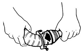
- Connecting the exhaust duct to the heater:
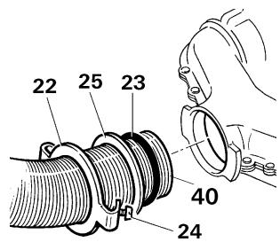
Slide sealing plate (22) about 3 cm onto the exhaust duct (with the claw pointing towards the heater exhaust outlet). Slide on pressure ring (25). Stretch open O-Ring (23) and carefully pass it over the cut edge of the duct. Then plug the exhaust duct into the exhaust outlet as far as the stop.
Slide the O-ring, pressure ring and sealing plate to the exhaust outlet. Twist on sealing plate (22) and fasten it securely by tightening screw (24).
A new O-ring (23) must be fitted each time the exhaust duct is dismantled.
-
Slide insulating duct (41) onto the exhaust duct (it must reach from the cowl to the rear wall of the installation box, refer to fig. E + D).
-
Fig. D + E: Take the ducting up the wall with as few bends as possible. Slide exhaust gas duct (40) into the cowl as far as the stop and secure with self-tapping screw (28).
Exhaust gas duct (40) with its insulating duct (41) must be sloping upward over its whole length and fitted securely and permanently with several clamps (42), otherwise a water trap may form, obstructing the free passage of the exhaust gases.
Gas connection
The operating pressure of the gas supply, 30 mbar (28 mbar butane/37 mbar propane) or 50 mbar must correspond to the operating pressure of the appliance (refer to name plate, fig. A e).
Fig. G: The gas supply pipe (32) must be connected using a cutting ring screw fitting with an outer diameter of 8 mm at the connecting piece (33).
The gas connection fitting on the heating appliance must not be bent! When tightening the connection nipple, hold it carefully in place with a second wrench!
Route the ducting in such a way that the heater can be removed for servicing work.
Make sure the gas lines are free of dirt, chips and such prior to connecting!
A special duct for internal gas connection is available on request. It is screwed onto gas connection fitting (33) with an elbow.
The gas system must accord with the technical and administrative provisions of the individual country of use (in Europe, for example, EN 1949 for motor vehicles).
National regulations and rulings (in Germany, for example, the DVGW worksheet G 607 for motor vehicles) must be respected.
Heater casing
- Fig. G: Push the handle connector (26), the piezo pressure igniter (27) if applicable, and the integrated operating element (51) for the Trumavent TEB fan into the cut-outs (take care to respect right-hand or left-hand installation). Close off any unoccupied cut-outs with the closure cover (50).
For Trumatic S 3002 P only: Plug the earthing cable (34) to the pressure igniter (27) and the earth contact (37) on the casing.
-
Press type plate (52) into the observation window opening (note right-handed or left-handed installation!).
-
With integrated control panel (51) plug connecting cable (53) of the Trumavent fan TEB into the control panel. Bend back strap (54) on the installation box and insert connecting cable (53).
For Trumatic S 3002 P only: Slide flat connector of ignition cable (38) on the connection (36) on the piezo ignitor (27) and slide on insulation (43 - refer to fig. A).
Trumatic S 3002 (P)
- Place the casing onto the lower retaining shackles. Guide the pressure rod (11) from below into the handle connector (26) and engage the casing at the top. Push the operating handle (55) from above onto the pressure bar (11) in such a way that the arrow points to the "0" position.
Trumatic S 5002
- Place the casing onto the lower retaining shackles. Guide the pressure rod (11) with operating handle (55) from below into the handle connector (26) and engage the case at the top.
Function check
After installation, the sealing tightness of the gas feed line must be tested in accordance with the pressure drop method. A test certificate (in Germany, for example, in accordance with the DVGW operational data sheet G 607) is to be issued.
Following this inspection, test all functions of the appliance as specified in the operating instructions.
The operating instructions and completed guarantee card are to be given to the owner of the vehicle.
Warning information
The installer or vehicle owner must display the yellow sticker with the warning information, enclosed with the appliance, in the vehicle so it is clearly visible to all users (e.g. on the wardrobe door)! Ask Truma to send you a sticker if necessary.
Special installation instructions
This heater is not to be installed in mobile homes intended for registration in Germany!
-
Cowl top T3 (art. no. 30700-03) must always be installed when the heater is operating - particularly when the vehicle is moving. It must be positioned in the unobstructed slipstream. If necessary, install a cowl extension AKV (art. no. 30010-20800).
-
If fresh air intake vents are installed they must be positioned so that air which has been polluted (such as by exhaust gases, petrol fumes or oil vapour) cannot find its way into the vehicle.
-
In exceptional cases dust penetration etc. may occur. For these cases we recommend installing a sealing kit: S 3002 (P) (art.no.30030-89800), S 5002 (art.no.30050-32700).
The camper manufacturer or heater installer must perform test drives to determine the combination of flue top and extensions (if required) for the individual as-delivered vehicle configurations and consult Truma if necessary. Depending on the vehicle model and the equipment installed on the roof, flue top T1 (art.no.30700-01) or T2 (art.no.30700-02) may be required.
Roof extensions and luggage stowed in the vicinity of the exhaust cowl impede the operation of the heater, especially when the vehicle is moving. The flame may flash back, causing damage to the heater and vehicle. In this case, additional cowl extensions must be used so that the top of the cowl projects at least 10cm above any objects. Failure to observe this will result in the refusal of any guarantee claim for resulting damage to the heater and vehicle.
- If the vehicle floor is given a body underseal, all parts of the heater located under the vehicle must be covered up so that the underseal spray does not impede the operation of the heater system. The covers must be removed again when the work is finished.
Trumatic S 3002 P
Trumatic S 3002
Trumatic S 5002
Chauffage à gaz
S 3002 (P): CE-0085AP0325
S 5002: CE-0085AP0326
S 3002 (P): CE-0085AP0325
S 5002: CE-0085AP0326
Solo Trumatic S 3002 P:
S 3002 (P): CE-0085AP0325
S 5002: CE-0085AP0326
- Installation instructions
- Installation and repair jobs on the heater are only to be carried out by an ex
- Intended use
- Approval
- Declaration of conformity:
- S 3002 (P): CE-0085AP0325
- S 5002: CE-0085AP0326
- Information regarding installation in Germany: This heater is not to be installed in motor vehicles (e.g. mobile homes) which are to be registered in Germany.
- Regulations
- The first year of operation must be marked on the name plate.
- Choice of location
- Installation cut-out:
- Preparatory work and installation boxes
- Installation of the heater
- Trumatic S 3002 P
- Trumatic S 3002
- Trumatic S 5002
- Exhaust gas cowl
- Trumatic S 3002 (P)
- Exhaust duct
- Gas connection
- Heater casing
- Function check
- Warning information
- Special installation instructions
- Solo Trumatic S 3002 P:
Brand : TRUMA
Model : TIC S 3002 P
Category : Motorhome heating